Return to International Power Technology Home Page
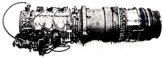
MODEL 501-KH |
|
SPECIFICATION 935A
|
INDUSTRIAL GAS
|
|
|
|
|
|
| Installation | 23038811 |
| Length | 90.0 in. (2286 mm) |
 |
| Height | 36.1 in. ( 917 mm) |
|
| Width | 32.2 in. ( 843 mm) |
| Basic Dry Weight | 1270 lb. (576.1 kg) |
The 501-KH engine is a single shaft gas turbine engine utilizing a 14-stage axial flow compressor; six combustion chambers within an annular combustor; a 4-stage turbine, of which the first stage is air cooled; and five main anti-friction pressure lubricated bearings. The compression ratio is approximately 9.3:1 at standard continuous rating conditions. Manifold flanges are provided on the outer combustion case for steam injection. The 501-KH engine is available in two configurations: (1) for operation with liquid fuel, (2) for operation with gaseous fuel. The specific fuel shall be reviewed by Allison prior to acceptance of the order. The fuel use shall be as specified in the purchase order.
| Ambient Temperature °F (°C) | 59 (15) |
| Ambient Pressure, S.L., psia (kPa) | 14.7 (101.4) |
| Engine Rotor Speed, rpm | 14,200 |
| Calculated Turbine Inlet Temp. (CTIT), °F (°C) | 1895 (1035) |
| NATURAL GAS1 | LIQUID FUEL1 | |
| Power Output2, hp (kW) | 5263 (3924) | 5106 (3807) |
| Specific Fuel Consumption, SFC2, Btu/shp-hr (kJ/kW-hr) |
8876 (12558) | 9100 (12875) |
NOTES:
1. See section 3.3 for fuel definition and
specifications.
2. Performance values are specified for new
engine deliveries from Allison
|
|
| SHP vs TAMB | Figure No. 1 |
| PS3 vs RPM | Figure No. 2 |
PERFORMANCE CHARACTERISTICS:
| GASEOUS FUEL | LIQUID FUEL | |
| SHP vs RPM (dry) | Figure No. 3 | Figure No. 15 |
| SHP vs RPM (steam injection) | Figure No. 4 | Figure No. 16 |
| WF vs RPM (dry) | Figure No. 5 | Figure No. 17 |
| WF vs RPM (steam injection) | Figure No. 6 | Figure No. 18 |
| WA vs RPM (dry) | Figure No. 7 | Figure No. 19 |
| WA vs RPM (steam injection) | Figure No. 8 | Figure No. 20 |
| W7 vs RPM (dry) | Figure No. 9 | Figure No. 21 |
| W7 vs RPM (steam injection) | Figure No. 10 | Figure No. 22 |
| TT7 vs RPM (dry) | Figure No. 11 | Figure No. 23 |
| TT7 vs RPM (steam injection) | Figure No. 12 | Figure No. 24 |
| PS3 vs RPM (dry) | Figure No. 13 | Figure No. 25 |
| PS3 vs RPM (steam injection) | Figure No. 14 | Figure No. 26 |
STARTING CHARACTERISTICS:
| TORQUE vs RPM | Figure No. 27 |
| Ambient Temperature °F (°C) | 59 (15) |
| Ambient Pressure, S.L., psia (kPa) | 14.7 (101.4) |
| Engine Rotor Speed, rpm | 14,200 |
| Calculated Turbine Inlet Temp. (CTIT), °F (°C) | 1800 (982) |
| Steam Flow lbs/sec (kg/sec) | 5.5 (2.50) |
| NATURAL GAS | LIQUID FUEL | |
| Power Output , hp (kW) | 7966 (5940) | 7855 (5857) |
| Specific Fuel Consumption, SFC , Btu/shp-hr (kJ/kW-hr) | 6447 (9121) | 6456 (9134) |
| NATURAL GAS | LIQUID FUEL | |
| Power Output , hp (kW) | 8002 (5967) | 7873 (5870) |
| Specific Fuel Consumption, SFC , Btu/shp-hr (kJ/kW-hr) | 7018 (9929) | 7041 (9962) |
|
3.3 Fuel (see also section 4.1 for additional requirements)
3.4 OilAllison EMS-35J, EMS-45, EMS-53, or MIL-L-23699B Synthetic Oil. Allison EMS-38 Mineral Oil may be approved for limited use on special request. Also, see Para. 4.2. Average Oil Consumption - 1/3 gallon (1.26 liter) per day 3.5 Estimated Sound Power Levels - Unsilenced
|
||||||||||||||||||||||||||||||||||||||||||||||||||||||||||||||||||||||||||
|
3.6 Altitude-Temperature Limits for Starting and Operating
3.7 Rotor Speed Operating Range
3.8 Gas Temperature Operating Limits, Calculated TIT (see Note 5.3)
3.9 Output Shaft Torque Limit
3.10 Shaft Horsepower Operating LimitEngine operation with steam injection shall not exceed the shaft horsepower limits specified on Figure No. 1. Line segment (1) on this figure is a torque limit and is not correctable to inlet pressure conditions. Line segments (2) and (3) are correctable to inlet pressure conditions. 3.11 Compressor Discharge Pressure Operating LimitEngine operation with steam shall not exceed the compressor discharge pressure limits specified on Figure No. 2. 3.12 Steam Flow Operating LimitThe maximum steam flow permitted to be injected into the engine shall be 5.5 lb/sec (2.5 kg/sec) provided that engine compressor discharge limits shown on Figure No. 2 are not exceeded. 3.13 Steam QualitySteam shall be dry and unsaturated. Steam shall be free of solid, liquid and gaseous contaminants to the extent that a representative sample of steam and carry over contaminants when collected, condensed and cooled would pass the water quality requirements of Allison EMS 124 and/or EMS 120D Type III water for continuous water injection. Boiler water carryover shall not be permitted and may result in a substantial decrease in engine life. 3.14 Exhaust EmissionsBased on factory tests, this engine when operating on specified liquid fuels, or on U.S. pipeline quality natural gas, is expected to meet Environmental Protection Agency Emissions Standards for New Stationary Gas Turbine Engines. (Ref. 40CFR60, Subpart G-G) Local environmental regulations may require more stringent control of exhaust emissions than those specified by the U.S. EPA. See water injection option for control of NOx emissions. Exhaust emissions and exhaust gas constituents for particular installation conditions will be established upon request. 3.15 Inlet Air QualityBased upon in house testing and operational experience inlet air quality has a direct effect upon the engine. It affects engine performance, compressor and turbine life, and the emission signature of the engine. For operational limits refer to the Installation Design Manual and contact Allison for advice.
|
|
4.0 ENGINE SYSTEMS4.1 fuel System
4.2 Lubrication System - Dry Sump
|
||||||||||||||||||||||||
|
Inlet Pressure:
|
|
|
Inlet Temp., max:
min: |
|
|
Filtration:
|
|
|
Flow:
|
|
|
Aeration:
|
|
|
Scavenge Back Pressure:
|
|
|
Heat Rejection:
|
|
|
Engine System Pressure:
|
|
|
4.3 Engine Control SystemThe engine is supplied with an electronic system that provides:
4.4 Temperature Measurement SystemThe temperature measurement system consists of 12 thermocouples, located at the turbine outlet, and an electronic control. Engine operator response is to a turbine inlet temperature (TIT) calculated by a portion of the electronic fuel control. Output voltage supplied as shown on the installation drawing for use with the customer indicator. 4.5 Ignition SystemThe ignition system consists of an ignition exciter and two igniter plugs. Electrical requirements are shown on the installation drawing. 4.6 Starting SystemStarter and Starter drive pad not included. Starting torque required is shown on Figure 27. 5.0 NOTES5.1 Acceptance TestEach engine shall be subject to an acceptance test. The test procedure, schedule, duration and performance determination method shall conform to Allison established commercial practice. The engine will be tested on a dry basis only (no steam injection). 5.2The performance ratings and estimated performance curves shown are based on the standard conditions specified, without inlet duct or exhaust losses, with no loading of accessory drives, no air being bled from the compressor air bleeds, 14,200 rpm and with a 700 sq. in. (0.45 sq. m) exit area exhaust diffuser as shown on the installation drawing with no air gap between diffuser and engine. 5.3The engine will produce, at a minimum, the rated power listed in paragraph 3.1.2 at a SFC no greater than that specified. 5.4Any installation of the 501-KH engine shall be in accordance with the 501-KH Installation Design Manual and shall be subject to review by Allison.
|
|
501-KH OPTIONSSee the Installation Design Manual and Installation Drawing for detail information regarding the available options. DUAL FUEL SYSTEM OPTIONEngine fitted with fuel and power control components for operating with either liquid or gaseous fuel. Fuel switchovers can be made with the engine at any power level up to and including standard continuous power. Switchovers at power can be made in 14 seconds or less. NOx EMISSION REDUCTION OPTIONA system is available to permit the introduction of water or other diluent into the engine for NOx reduction. |
Return to International Power Technology Home Page
|
|